GPIO & Real Boards
So far we have been running all our code using the arduino-feather-nrf52840-sense board.
In this tutorial, we will learn how to use the GPIO pins on a real board to control LEDs or read button presses.
For this tutorial we will be using a the arduino-feather-nrf52840-sense board
with the Teamagochi PCB,
but you can use any board that has GPIO pins.
Step 1: Configuring our Board
Section titled “Step 1: Configuring our Board”First, we need to inform RIOT about the board we are using.
To do this we adapt the BOARD variable in our Makefile to the board we are using.
BOARD ?= arduino-feather-nrf52840-sense# name of your applicationAPPLICATION = gpio_example
# Change this to your board if you want to build for a different boardBOARD ?= arduino-feather-nrf52840-sense
# This has to be the absolute path to the RIOT base directory:# If you are following the tutorial, your RIOT base directory will# most likely be something like RIOTBASE ?= $(CURDIR)/RIOT# instead of thisRIOTBASE ?= $(CURDIR)/../../..
# Comment this out to disable code in RIOT that does safety checking# which is not needed in a production environment but helps in the# development process:DEVELHELP ?= 1
# Change this to 0 show compiler invocation lines by default:QUIET ?= 1
include $(RIOTBASE)/Makefile.includeTry flashing the board with make flash and see if it works,
it should still execute the same code as before when running RIOT natively on your
own hardware but now using the actual board.
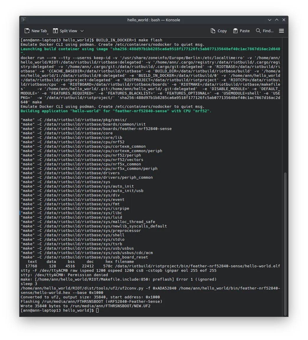
Now if we type make term we should see the output of the board in the terminal.
Make sure that you have the board connected to your computer via USB and
that your user has the necessary permissions to access the serial port.
Step 2: Controlling LEDs
Section titled “Step 2: Controlling LEDs”Now that we have the board working, let’s try to control the LEDs on the board.
The exact pins that control the LEDs might vary depending on the board you are using,
but in the case of the arduino-feather-nrf52840-sense board,
the LED would be connected on Port 1 Pin 9.
You can often find these defines either in the board schematics or in the board configuration headers in RIOT.
First we need to include the necessary modules in our projects Makefile.
# Add the gpio module to the buildUSEMODULE += periph_gpioUSEMODULE += periph_gpio_irq
# Enable the milliseconds timer.USEMODULE += ztimerUSEMODULE += ztimer_msec# name of your applicationAPPLICATION = gpio_example
# Change this to your board if you want to build for a different boardBOARD ?= arduino-feather-nrf52840-sense
# This has to be the absolute path to the RIOT base directory:# If you are following the tutorial, your RIOT base directory will# most likely be something like RIOTBASE ?= $(CURDIR)/RIOT# instead of thisRIOTBASE ?= $(CURDIR)/../../..
# Comment this out to disable code in RIOT that does safety checking# which is not needed in a production environment but helps in the# development process:DEVELHELP ?= 1
# Add the gpio module to the buildUSEMODULE += periph_gpioUSEMODULE += periph_gpio_irq
# Enable the milliseconds timer.USEMODULE += ztimerUSEMODULE += ztimer_msec
# Change this to 0 show compiler invocation lines by default:QUIET ?= 1
include $(RIOTBASE)/Makefile.includeThis allows us to both control the GPIO pins and timers.
Specifically, we need the periph_gpio module to control the GPIO pins,
periph_gpio_irq to handle GPIO interrupts,
and ztimer to use the timer functionality for blinking the LED.
In this case, we also need the ztimer_msec module to use the millisecond timer.
Now we need to actually define the pin that we want to control in our code.
To do this include the following lines before the main function.
#include "board.h"#include "periph/gpio.h"#include "ztimer.h"
/* Define the LED0 pin and mode */gpio_t led0 = GPIO_PIN(1, 9);gpio_mode_t led0_mode = GPIO_OUT;
Now we can control the LED. First we initialize the pin and afterwards we turn the LED off by clearing the pin.
int main(void){    /* Initialize the LED0 pin */    gpio_init(led0, led0_mode);    /* Turn off the LED0 pin */    gpio_clear(led0);
    /* Loop forever */    while (1) {
    }}
Turning the LED off when the board starts is quite boring, so let’s make it blink by adding a delay and toggling the LED.
/* Loop forever */ while (1) { /* Toggle the LED0 pin every 500 milliseconds */ gpio_toggle(led0); ztimer_sleep(ZTIMER_MSEC, 500); }The full code should now look like this:
#include "board.h"#include "periph/gpio.h"#include "ztimer.h"
/* Define the LED0 pin and mode */gpio_t led0 = GPIO_PIN(1, 9);gpio_mode_t led0_mode = GPIO_OUT;
int main(void){    /* Initialize the LED0 pin */    gpio_init(led0, led0_mode);    /* Turn off the LED0 pin */    gpio_clear(led0);
    /* Loop forever */    while (1) {        /* Toggle the LED0 pin every 500 milliseconds */        gpio_toggle(led0);        ztimer_sleep(ZTIMER_MSEC, 500);    }}
If we now make flash and then make term we should see the LED blinking.
Step 3: Reading Button Presses
Section titled “Step 3: Reading Button Presses”If you remember what we did in the timers tutorial, we can use quite similar code to read button presses.
On a constrained device you usually don’t want to poll the button state, which is why we will use an interrupt to detect the button press, that way we can drastically reduce the power consumption of the device.
First we need to define the callback function that will be called when the button is pressed.
/* This callback function will be called when the button state changes */void button_callback(void *arg){    /* the argument is not used */    (void)arg;
    /* Toggle the LED1 pin based on the button state */    if (gpio_read(button)) {        gpio_clear(led1);    }    else {        gpio_set(led1);    }}
Now we need to define the button and led1 pin and mode and initialize it.
#include "board.h"#include "periph/gpio.h"#include "ztimer.h"
/* Define the LED0 pin and mode */gpio_t led0 = GPIO_PIN(1, 9);gpio_mode_t led0_mode = GPIO_OUT;
/* Define the LED1 pin and mode */gpio_t led1 = GPIO_PIN(1, 10);gpio_mode_t led1_mode = GPIO_OUT;
/* Define the button pin */gpio_t button = GPIO_PIN(1, 2);
/* This callback function will be called when the button state changes */void button_callback(void *arg){    /* the argument is not used */    (void)arg;
    /* Toggle the LED1 pin based on the button state */    if (gpio_read(button)) {        gpio_clear(led1);    }    else {        gpio_set(led1);    }}
int main(void){    /* Initialize the LED0 pin */    gpio_init(led0, led0_mode);    /* Turn off the LED0 pin */    gpio_clear(led0);
    /* Initialize the LED1 pin */    gpio_init(led1, led1_mode);    /* Turn off the LED1 pin */    gpio_clear(led1);
    /* Initialize the button pin */    gpio_init_int(button, GPIO_IN_PU, GPIO_BOTH, button_callback, NULL);
    /* Loop forever */    while (1) {        /* Toggle the LED0 pin every 500 milliseconds */        gpio_toggle(led0);        ztimer_sleep(ZTIMER_MSEC, 500);    }}
This code will initialize the button pin and call the button_callback
function whenever the button is pressed.
If we now make flash and then make term we should see the LED turn on
when the button is pressed.
Extra: Board Specific Defines
Section titled “Extra: Board Specific Defines”Most boards (if they have LEDs or buttons) will have
specific defines for the GPIO pins that are used.
For example, the arduino-feather-nrf52840-sense board has the LED0_TOGGLE
define that allows you to toggle the LED without having to define the pin yourself.
In most cases using gpio like we did in this tutorial is the best way to go, it’s more flexible, documented and standardized for all boards. However, using these defines can often be easier at the start, esp. when the GPIO pins are not documented well or the board support is not complete yet.
Using this define, we can simplify our code to the following:
int main(void){    /* Initialize the LED0 pin */    gpio_init(led0, led0_mode);    /* Turn off the LED0 pin */    gpio_clear(led0);
    /* Loop forever */    while (1) {        /* Toggle the LED0 pin every 500 milliseconds */        LED0_TOGGLE;        ztimer_sleep(ZTIMER_MSEC, 500);    }}
Conclusion
Section titled “Conclusion”In this tutorial we learned how to use the GPIO pins on a real board to control LEDs and read button presses.
This is a very basic example, but it should give you a good starting point to build more complex applications.