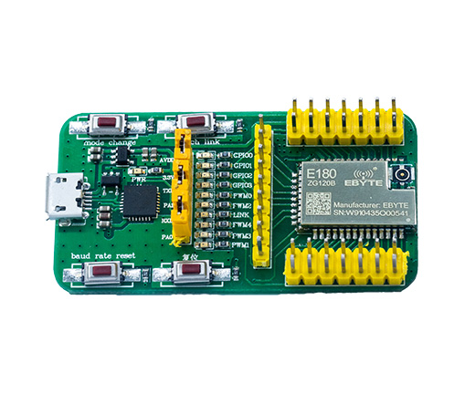
Ebyte E180-ZG120B-TB Test Board
Support for Ebyte E180-ZG120B-TB Test Board
Support for Ebyte E180-ZG120B-TB Test Board
Overview
Ebyte E180-ZG120B Test Board is equipped with the EFM32 microcontroller. It is specifically designed for low-power applications, having energy-saving peripherals, different energy modes and short wake-up times.
Hardware
MCU
| MCU | EFR32MG1B232F256GM32 |
|---|---|
| Family | ARM Cortex-M4F |
| Vendor | Ebyte |
| Vendor Family | EFM32 Mighty Gecko 1B |
| RAM | 32.0 KiB (1.0 KiB reserved by radio blob) |
| Flash | 256.0 KiB |
| EEPROM | no |
| Frequency | up to 38.4 MHz |
| FPU | yes |
| MPU | yes |
| DMA | 8 channels |
| Timers | 2x 16-bit + 1x 16-bit (low power) |
| ADCs | 12-bit ADC |
| UARTs | 2x USART, 1x LEUART |
| SPIs | 2x USART |
| I2Cs | 1x |
| Vcc | 1.85 V - 3.8 V |
| Datasheet | Datasheet |
| Manual | Manual |
| Board Manual | Board Manual |
Pin Mapping
Warning: At least for revision 10199-V1.0 of the test board most of the
silkscreen labels are incorrect.
Note: Everything here assumes the board is oriented so that the USB connector is on the top.
Right Header
(Top-left pin is 1, top-right pin is 2, and so on.)
| Description | Pin (left) | Pin (right) | Description |
|---|---|---|---|
| GND | 1 | 2 | VCC |
| PB13 | 3 | 4 | PB12 |
| PB11 | 5 | 6 | PD15 |
| NC (pin 8 on E180-ZG120B) | 7 | 8 | NC (pin 7 on E180-ZG120B) |
| PA1 | 9 | 10 | PA0 |
| PD14 | 11 | 12 | PD13 |
| GND | 13 | 14 | GND |
Top Header
(Leftmost pin is 1, second from left is 2, and so on.)
| Description | Pin (left to right) |
|---|---|
| NC (pin 23 on E180-ZG120B) | 1 |
| NC (pin 22 on E180-ZG120B) | 2 |
| PC11 | 3 |
| NC (pin 20 on E180-ZG120B) | 4 |
| PF2 | 5 |
| PC10 | 6 |
| NC (pin 17 on E180-ZG120B) | 7 |
| NC (pin 16 on E180-ZG120B) | 8 |
| NC (pin 16 on E180-ZG120B) | 9 |
Left Header
(Top-left pin is 1, top-right pin is 2, and so on.)
| Description | Pin (left) | Pin (right) | Description |
|---|---|---|---|
| NC (pin 24 on E180-ZG120B) | 1 | 2 | SWCLK |
| SWDIO | 3 | 4 | PB14 |
| PB15 | 5 | 6 | NC (pin 29 on E180-ZG120B) |
| PF3 | 7 | 8 | NC (pin 31 on E180-ZG120B) |
| NC (pin 32 on E180-ZG120) | 9 | 10 | NC (pin 33 on E180-ZG120B) |
| NC (pin 34 on E180-ZG120) | 11 | 12 | NC (pin 35 on E180-ZG120B) |
| GND | 13 | 14 | Reset |
Peripheral mapping
| Peripheral | Number | Hardware | Pins | Comments |
|---|---|---|---|---|
| ADC | 0 | ADC0 | CHAN0: internal temperature | Ports are fixed, 14/16-bit resolution not supported |
| HWCRYPTO | — | — | AES128/AES256, SHA1, SHA256 | |
| RTT | — | RTCC | 1 Hz interval. Either RTT or RTC (see below) | |
| RTC | — | RTCC | 1 Hz interval. Either RTC or RTT (see below) | |
| Timer | 0 | TIMER0 + TIMER1 | TIMER0 is used as prescaler (must be adjacent) | |
| 1 | LETIMER0 | |||
| UART | 0 | USART0 | RX: PA1, TX: PA0 | Default STDIO output |
User interface
| Peripheral | Mapped to | Pin | Comments |
|---|---|---|---|
| Button | PB0_PIN | PD15 | Mode Change |
| PB1_PIN | PD13 | Touch Link | |
| PB2_PIN | PB11 | Baud Rate Reset | |
| LED | LED0_PIN | PF2 | GPIO2 LED |
| LED1_PIN | PF3 | Link LED |
The fourth button with the Chinese description is the reset button.
Implementation Status
| Device | ID | Supported | Comments |
|---|---|---|---|
| MCU | EFR32MG1B | yes | Power modes supported |
| Low-level driver | ADC | yes | |
| Flash | yes | ||
| GPIO | yes | Interrupts are shared across pins (see reference manual) | |
| HW Crypto | yes | ||
| I2C | yes | ||
| PWM | yes | ||
| RTCC | yes | As RTT or RTC | |
| SPI | partially | Only master mode | |
| Timer | yes | ||
| UART | yes | USART is shared with SPI. LEUART baud rate limited (see below) | |
| USB | no |
Board configuration
Clock selection
There are several clock sources that are available for the different peripherals. You are advised to read AN0004.0 to get familiar with the different clocks.
| Source | Internal | Speed | Comments |
|---|---|---|---|
| HFRCO | Yes | 19 MHz | Enabled during startup, changeable |
| HFXO | No | 38.4 MHz | |
| LFRCO | Yes | 32.768 kHz | |
| LFXO | No | 32.768 kHz | |
| ULFRCO | No | 1 kHz | Not very reliable as a time source |
The sources can be used to clock following branches:
| Branch | Sources | Comments |
|---|---|---|
| HF | HFRCO, HFXO | Core, peripherals |
| LFA | LFRCO, LFXO | Low-power timers |
| LFB | LFRCO, LFXO, CORELEDIV2 | Low-power UART |
| LFE | LFRCO, LFXO | Real-time Clock and Calendar |
CORELEDIV2 is a source that depends on the clock source that powers the core. It is divided by 2 or 4 to not exceed maximum clock frequencies (EMLIB takes care of this).
The frequencies mentioned in the tables above are specific for this starter kit.
It is important that the clock speeds are known to the code, for proper
calculations of speeds and baud rates. If the HFXO or LFXO are different from
the speeds above, ensure to pass EFM32_HFXO_FREQ=freq_in_hz and
EFM32_LFXO_FREQ=freq_in_hz to your compiler.
You can override the branch’s clock source by adding CLOCK_LFA=source to your
compiler defines, e.g. CLOCK_LFA=cmuSelect_LFRCO.
Low-power peripherals
The low-power UART is capable of providing an UART peripheral using a low-speed clock. When the LFB clock source is the LFRCO or LFXO, it can still be used in EM2. However, this limits the baud rate to 9600 baud. If a higher baud rate is desired, set the clock source to CORELEDIV2.
Note: peripheral mappings in your board definitions will not be affected by this setting. Ensure you do not refer to any low-power peripherals.
RTC or RTT
RIOT-OS has support for Real-Time Tickers and Real-Time Clocks.
However, this board MCU family has support for a 32-bit Real-Time Clock and Calendar, which can be configured in ticker mode or calendar mode. Therefore, only one of both peripherals can be enabled at the same time.
Configured at 1 Hz interval, the RTCC will overflow each 136 years.
Hardware crypto
This MCU is equipped with a hardware-accelerated crypto peripheral that can speed up AES128, AES256, SHA1, SHA256 and several other cryptographic computations.
A peripheral driver interface is proposed, but not yet implemented.
Usage of EMLIB
This port makes uses of EMLIB by Ebyte to abstract peripheral registers. While some overhead is to be expected, it ensures proper setup of devices, provides chip errata and simplifies development. The exact overhead depends on the application and peripheral usage, but the largest overhead is expected during peripheral setup. A lot of read/write/get/set methods are implemented as inline methods or macros (which have no overhead).
Another advantage of EMLIB are the included assertions. These assertions ensure
that peripherals are used properly. To enable this, pass DEBUG_EFM to your
compiler.
Pin locations
The EFM32 platform supports peripherals to be mapped to different pins
(predefined locations). The definitions in periph_conf.h mostly consist of a
location number and the actual pins. The actual pins are required to configure
the pins via GPIO driver, while the location is used to map the peripheral to
these pins.
In other words, these definitions must match. Refer to the data sheet for more information.
This MCU has extended pin mapping support. Each pin of a peripheral can be connected separately to one of the predefined pins for that peripheral.
Flashing the device
The board has no integrated programmer/debugger and no bootloader. Hence,
an external SWD programmer/debugger such as the SEGGER JLink
or the ST-Link is required. Connect at least the SWDIO, SWCLK,
and GND to the programmer. If JLinkExe is found in $PATH, jlink is used
by default for flashing, otherwise openocd is the default. When using OpenOCD,
the stlink is the default for OPENOCD_DEBUG_ADAPTER; provide a different
value if you use other hardware.
Note: When flashing with OpenOCD, leave the NRESET pin unconnected. The configuration does a soft reset only to work around an issue attaching with the hardware reset signal.
Flashing is supported by RIOT-OS using the command below:
BOARD=e180-zg120b-tb make flashTo run the GDB debugger, use the command:
BOARD=e180-zg120b-tb make debugOr, to connect with your own debugger:
BOARD=e180-zg120b-tb make debug-serverSome boards have (limited) support for emulation, which can be started with:
BOARD=e180-zg120b-tb make emulateLicense information
Ebyte’ EMLIB: zlib-style license (permits distribution of source).