LimiFrog Version 1
Support for the limifrog-v1 board
Support for the limifrog-v1 board
Overview
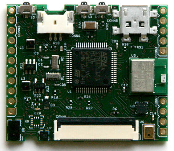
LimiFrog-v1 arose from the La BlueFrog board. LimiFrog-v1 contains the first hardware revision of that kickstarter project. LimiFrog-v2 is already there and the RIOT support will follow. LimiFrog features a variety of sensors as well as an OLED Display and a BLE (Bluetooth Low-Energy) module.
Hardware
MCU
| MCU | STM32L151RC |
|---|---|
| Family | ARM Cortex-M3 |
| Vendor | ST Microelectronics |
| RAM | 32KiB |
| Flash | 256KiB |
| Frequency | 32MHz (no external oscillator connected) |
| FPU | no |
| Timers | 8 (8x 16-bit, 1x 32-bit [TIM5]) |
| ADCs | 1x 42-channel 12-bit |
| UARTs | 3 |
| SPIs | 2 |
| I2Cs | 2 |
| Vcc | 1.65V - 3.6V |
| Datasheet | Datasheet |
| Reference Manual | Reference Manual |
| Programming Manual | Programming Manual |
User Interface
2 Buttons:
| PIN |
|---|
| PA15 (IN) |
| PC8 (IN) |
1 LED:
| NAME | LED_RED |
|---|---|
| Color | red |
| Pin | PC3 |
Implementation Status
| Device | ID | Supported | Comments |
|---|---|---|---|
| MCU | STM32L151RC | partly | Energy saving modes not fully utilized |
| Low-level driver | GPIO | yes | |
| PWM | yes | ||
| UART | yes | ||
| I2C | yes | ||
| SPI | yes | ||
| Timer | yes | ||
| Ambient Light Sensor | ST VL6180X | no | planned |
| Accelerometer | ST LSM6DS3 | no | planned |
| Magnetometer | ST LIS3MDL | no | planned |
| Gyroscope | ST LSM6DS3 | no | planned |
| atmospheric pressure (and altitude) sensor | ST SLPS25H | no | planned |
| Microphone | Knowles SPU0414HR5H-SB | no | planned |
| OLED Display | Densitron DD-160128FC-1A | no | planned |
| BLE | Panasonic PAN1740 | no | planned |
Flashing and Debugging the device
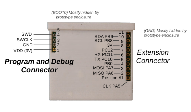
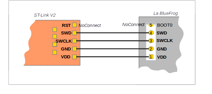
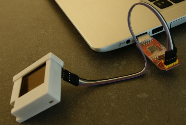
The LimiFrog-v1 has no on-board programmer nor an USB-UART converter. It can be programmed by using the integrated ST-Link/V2 programmer of any STM32Fx- discovery board. See the Hardware subsection in Flashing and Debugging section here for an example. Another way is to use a stand-alone ST-Link V2 programmer as shown in the picture.
To debug the device you may also want to use a stand-alone UART converter and connect it to the pins PC10 and PC11 and keep the programmer plugged.