Seeed Studio Xiao ESP32C3
Support for the Seeed Studio Xiao ESP32-C3 board
Support for the Seeed Studio Xiao ESP32-C3 board @author David Picard
\section seeedstudio-xiao-esp32c3 Seeed Studio Xiao ESP32C3
Overview
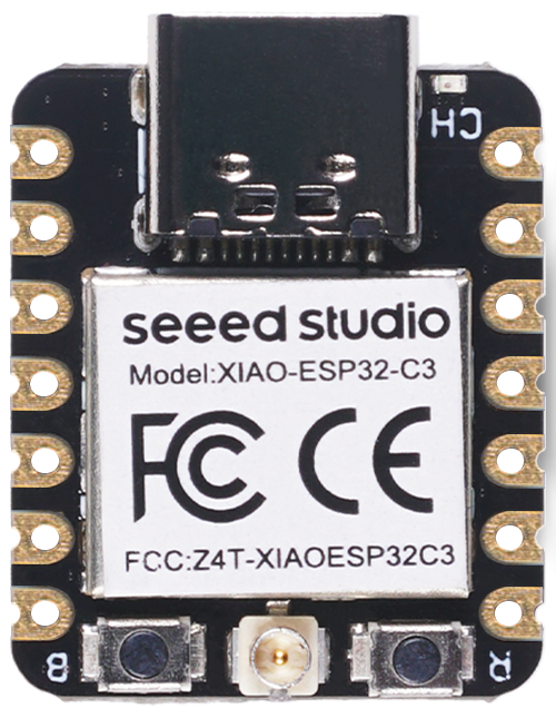
Seeed Studio Xiao ESP32C3 is an IoT mini development board based on the Espressif ESP32-C3 WiFi/Bluetooth dual-mode chip, featuring a single core 32-bit RISC-V CPU that operates at up to 160 MHz.
- Wi-Fi
- Bluetooth
- Battery charging chip: Supports lithium battery charge and discharge management
- Memory: 400KB of SRAM, and 4MB of on-board flash memory
- Small size: 21 x 17.8mm
- Ultra-Low Power: Deep sleep power consumption is about 43μA
- Battery charge indicator red LED
Hardware
MCU
Most features of the board are provided by the ESP32-C3 SoC. For detailed information about the ESP32-C3 variant (family) and ESP32x SoCs, see section esp32_mcu_esp32 “ESP32 SoC Series”.
Board Configuration
The Seeed Studio EPS32-C3 Xiao board has a reset button and a bootloader button, but no LED. After reset, the bootloader button may be used by the application.
To select the board, add the following to the make command line:
BOARD=seeedstudio-xiao-esp32c3 make ...GPIO overview:
- 3 x ADC channels at maximum
- 1 x SPI
- 1 x I2C
- 1 x UART
- 11 x PWM channels (only 3 defined by default)
The purpose for which a GPIO is used depends on which module
or function is used first. For example, if module periph_spi is not used,
the GPIOs listed in SPI configuration can be used for other purposes.
The following table shows the default board configuration. This configuration can be overridden by esp32_application_specific_configurations “application-specific configurations”.
**Note:** The configuration of ADC channels contains all ESP32-C3 GPIOs that could be used as ADC channels.
Note: BUTTON0 conflicts with the SPI MISO line. If the SPI module is enabled, the button will be automatically disabled.
For detailed information about the peripheral configurations of ESP32-C3 boards, see section esp32_peripherals “Common Peripherals”.
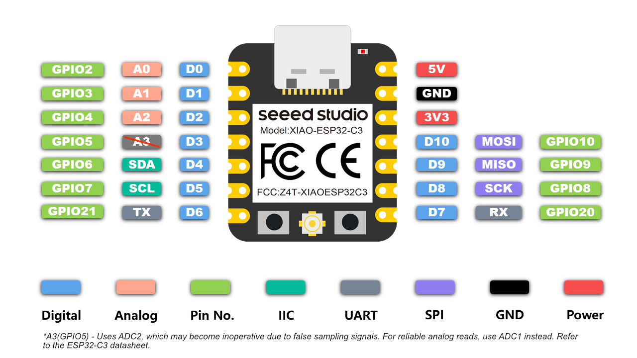
Board Pinout
The following figures show the pinouts as configured by default board definition.
Board documentation
- schematic (PDF)
- pinout (XLSX)
- ESP32-C3 datasheet (PDF)
- ESP32-C3 Technical Reference Manual (PDF)
- power consumption report (PDF)
- product page
- wiki page
Flashing the Device
The USB-C connector of the board is directly connected to the USB Serial/JTAG interface of the ESP32-C3 SoC. It can be used to program the board and to debug the application. Just connect the board to your host computer and use the following command:
BOARD=seeedstudio-xiao-esp32c3 make flash ...The make utility will normally restart the board in download mode in order to flash it. But, on occasion, this reset doesn’t work. The programmer can’t connect to the board and the flashing operation is aborted with a timeout error:
Serial port /dev/ttyACM0Connecting......serial.serialutil.SerialTimeoutException: Write timeoutIn this situation, restart the board manually in download mode:
- hold down the BOOT button
- press and release the RESET button
- release the BOOT button.
After flashing the board, it will still be in download mode. You have to press the RESET button to start your application.
For detailed information about ESP32-C3 as well as configuring and compiling RIOT for ESP32-C3 boards, see esp32_riot.