STM32F3Discovery
Support for the STM32F3Discovery board
Overview
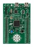
The STM32F3-discovery is cheap evaluation board designed by ST for pushing the STM32F3 microcontoller to a broad audience. It features an STM32F303VC microcontroller with 48Kb of RAM and 256Kb flash memory running with up to 72MHz. Addionially it provides USB host capabilities, 8 LEDs and sensors for a 9-degree of freedom initial measurement unit (3-axis accelerometer, 3-axis gyro and 3-axis magnetometer).
The board does however not provide any radio capabilities, radio devices have to be connected externally via I2C, SPI, UART or similar.
See this page for a quick getting started guide.
Hardware
MCU
| MCU | STM32F303VC |
|---|---|
| Family | ARM Cortex-M4 |
| Vendor | ST Microelectronics |
| RAM | 48Kb (40Kb RAM + 8Kb CCM RAM) |
| Flash | 256Kb |
| Frequency | up to 72MHz (using the on-board 8MHz Oszillator of the ST-Link) |
| FPU | yes |
| Timers | 10 (9x 16-bit, 1x 32-bit [TIM2]) |
| ADCs | 4x 12-bit |
| UARTs | 5 |
| SPIs | 3 |
| I2Cs | 2 |
| Vcc | 2.0V - 3.6V |
| Datasheet | Datasheet |
| Reference Manual | Reference Manual |
| Programming Manual | Programming Manual |
| Board Manual | Board Manual |
RIOT static pin mapping
please refer to this
- document for the pin mapping as
implemenented in
boards/stm32f3discovery/include/periph_conf.h
User Interface
2 Buttons:
| NAME | USER | RESET |
|---|---|---|
| Pin | PA0 (IN) | NRST |
8 LEDs:
| NAME | LD3 | LD4 | LD5 | LD6 | LD7 | LD8 | LD9 | LD10 |
|---|---|---|---|---|---|---|---|---|
| Color | red | blue | orange | green | green | orange | blue | red |
| Pin | PE9 | PE8 | PE10 | PE15 | PE11 | PE14 | PE12 | PE13 |
E-Compass / Accelerometer
The board has an on-board MEMS-chip that is an integrated accelerometer and e-compass.
| Sensor | LSM303DLHC |
|---|---|
| Type | Accelerometer and magnetometer |
| Vendor | ST Microelectronics |
| Datasheet | Datasheet |
| Connected to | I2C_0 |
| Pin Config: | |
| Device | I2C1 |
| SCL | PB6 (OUT, I2C1_SCL) |
| SDA | PB7 (OUT, I2C1_SDA) |
| DRDY | PE2 (IN) |
| INT1 | PE4 (IN) |
| INT2 | PE5 (IN) |
Gyroscope
An 3-axis gyroscope is soldered on the board.
| Sensor | L3GD20/I3G4250D [1] |
|---|---|
| Type | Gyroscope |
| Vendor | ST Microelectronics |
| Datasheet L3GD20 | Datasheet |
| Datasheet I3G4250D | Datasheet |
| Connected to | SPI_0 |
| Pin Config: | |
| Device | SPI1 |
| SCK | PA5 (OUT, SPI1_SCK) |
| MISO | PA6 (IN, SPI1_MISO) |
| MOSI | PA7 (OUT, SPI1_MOSI) |
| CS | PE3 (OUT) |
| INT1 | PE0 (IN) |
| INT2/DRDY | PE1 (IN) |
[1] L3GD20 (up to rev. D01), IG34250D (from rev. E02) The driver detects automatically which sensor variant is on the board.
Implementation Status
| Device | ID | Supported | Comments |
|---|---|---|---|
| MCU | STM23F303VC | partly | Energy saving modes not fully utilized |
| Low-level driver | GPIO | yes | |
| PWM | yes | ||
| UART | full | ||
| I2C | no | in progress | |
| SPI | no | in progress | |
| USB | no | ||
| Timer | full | ||
| Inpute Capture | no | ||
| Accelerometer | LSM303DLHC | no | planned |
| Magnetometer | LSM303DLHC | no | planned |
| Gyroscope | L3GD20/I3G4250D | yes |
Flashing the device
The STM32F3discovery board includes an on-board ST-LINK V2 programmer. The easiest way to program the board is to use OpenOCD. Once you have installed OpenOCD (look here for installation instructions), you can flash the board simply by typing
make flashand debug via GDB by simply typing
make debugSupported Toolchains
For using the STM32F3discovery board we strongly recommend the usage of the GNU Tools for ARM Embedded Processors toolchain.
Using UART
- connect your usb tty to: RX=PA10 TX=PA9 and GND=GND
- PA10 is connected with TX on the UART converter
- PA9 is connected with RX on the UART converter
- done