Zigduino
Support for the Zigduino board
Support for the Zigduino board
Hardware
Pinout
Warning: Unlike on other ATmega MCUs, the GPIOs are not 5V tolerant.
Note: The 5V pin cannot be used to power the board, as the board is not equipped with an voltage regulator. The pin is therefore not connected. But it can be used to pass 5V to shields, if connected to a 5V supply voltage.
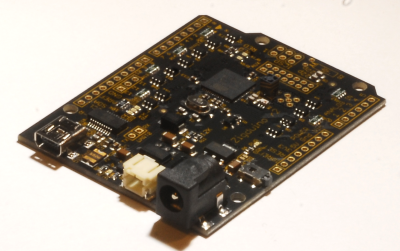
Board
The Zigduino board is an Arduino-compatible microcontroller platform that integrates a SOC with a 8-Bit AVR MCU and a IEEE 802.15.4 radio chip (ATmega128RFA1).
MCU Details
| MCU | ATmega128RFA1 |
|---|---|
| Family | ATmega |
| Vendor | Atmel |
| Package | QFN/MLF |
| SRAM | 16KiB |
| Flash | 128KiB |
| EEPROM | 4KiB |
| Core Frequency | 8MHz (16MHz no power save mode) |
| Oscillators | 32.768 kHz & 16 MHz |
| Timer | 6 ( 2x8bit & 4x16bit ) |
| Analog Comparator | 1 |
| ADCs | 1x 15 channel 6 to 12-bit |
| USARTs | 2 |
| SPIs | 3 (1 SPI & 2 USART SPI) |
| I2Cs | 1 (called TWI) |
| Vcc | 1.8V - 3.6V |
| Datasheet / Reference Manual | Datasheet and Reference Manual |
| Board Manual | Product Page |
The MCU comes with a 2.4 GHz IEEE 802.15.4 radio that is compatible with the Atmel AT86RF23x line of transceivers with the only difference being that it is not being accessed over an SPI bus, but instead the radio registers are directly mapped into memory.
Flashing RIOT
Flashing RIOT on the Zigduino is done using the on-board USB-TTL adapter. The ATmega bootloader is present on the MCU. Simply use
make flash BOARD=zigduino
Use on IoT Lab
Most of the Zigduino nodes are deployed in the Strasbourg site with sensors. Some of these nodes are also combined with a LoRa modem in order to offer a dual radio stack IEEE 802.15.4/LoRaWAN.
There are two available configurations:
Zigduino (atmega128rfa1)
A basic Zigduino nodes with embedded sensors:
- Grove Temperature Humidity sensor (pin 14, A0)
- Grove Light sensor (pin 15, A1)
- Grove Loudness sensor (pin 16, A2)
- Grove PIR Motion sensor (pin 4, D4)
Zigduino (atmega128rfa1_rn2483)
This is an extension of the previous Zigduino (atmega128rfa1)
- Secondary serial port (LoRa modem): 57600 bauds
- RN2483 modem with 1.0.3 firmware (LoRaWAN Class A only)
- TX (pin 1, TXD1)
- RX (pin 0, RXD1)